Mechanism
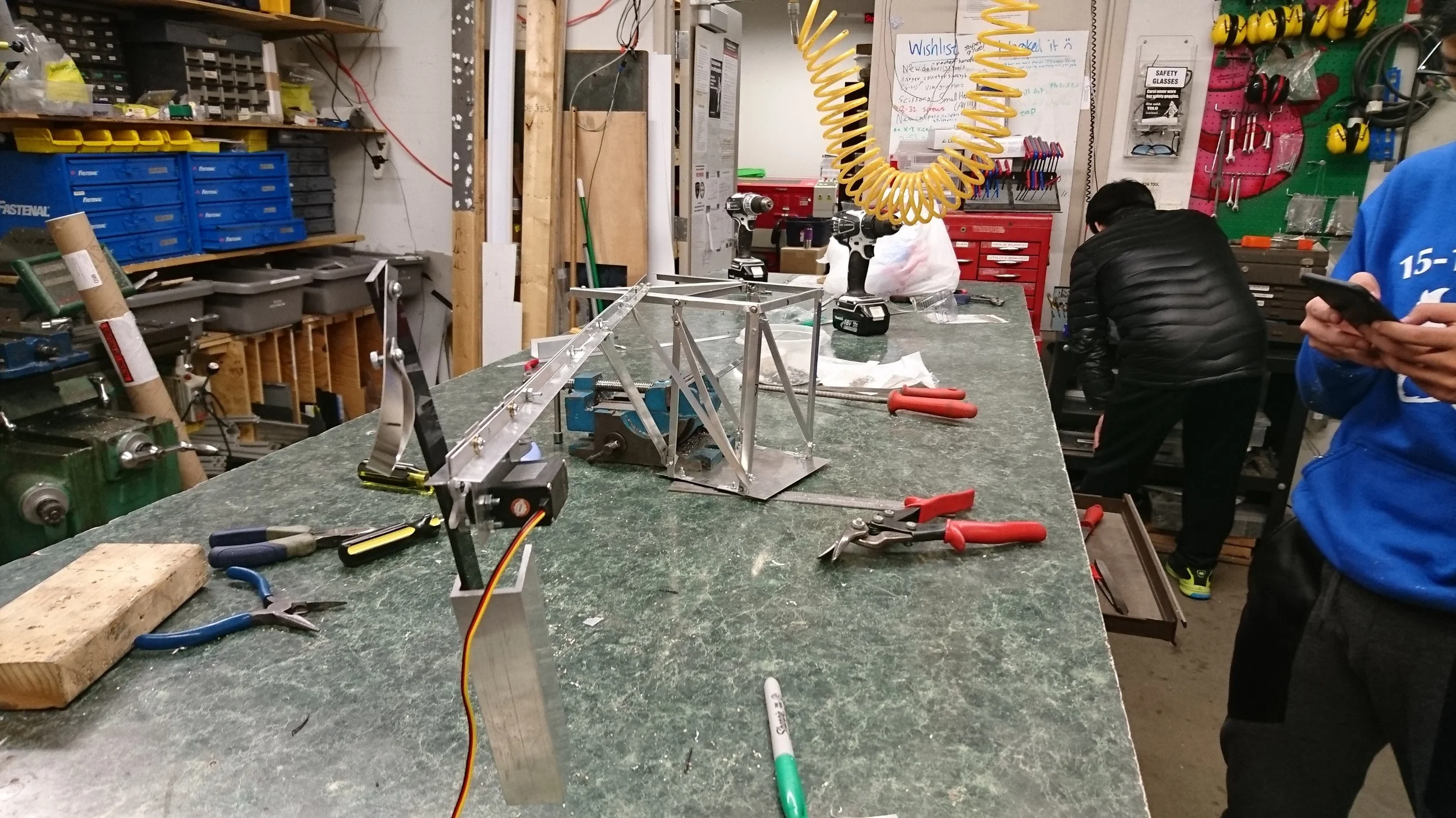
Our crane lifts by having the motor turn a lever arm attached on one side to a counterweight, and another connected to a hook, which hooks onto the 1lb weight that we intend to lift. The hook is free to spin around so that the motor always provides an upward force on the weight.
The lifting mechanism is supported by an arm attached to a base. The arm is a T-beam, formed by attaching 2 L-beams bent 90 degrees. The T-beam should have a high second moment of inertia to reduce bending. The base is a rectangular prism with an overhang supported along the diagonals to ensure rigidity. The overhang is where the arm attached to the base by four bolts, effectively acting as 2 pins.
Upper limit

red line circles our two supports

The upper limit assumes that the base is rigid, and that the arm is supported by pins at the bass and the furthest support. Using engineering tables, we have

Lower Limit

The lower limit assumes that everything is rigid until the end of the furthest support. Using tables, we have

The actual deflection is slightly higher than the upper limit we calculated due to the fact that neither our base nor our supports are fully rigid. Their slight deflections amounted to an angle change in the arm, resulting in a higher vertical deflection downwards.
Performance