Ship Welding Robot
I worked at CERLAB CMU on the ship welding robot team from January 2016 to May 2018. Below are our goal and the reason we are passionate about this project:
We want to automate the ship building process
Shipbuilders need to weld different compartments together
Used to be done manually in confined space inside compartments
Help Tsuneishi to develop ship welding robot to automate the process
Challenge
•Need to get through longis, manholes, curved surface as shown above
•Able to perform accurate, consistent welding under tough conditions, which is needed between compartments, longis and the ground
•Perform the welding automatically, meaning the robot would need to locate itself and navigate automatically

CAD for working environment of the welding robot

Problem Definition: Red part is mainly what I am responsible for

Concept Generation
When I joined the group, we were still in the stage of concept generation and just finished the first prototyping stage.
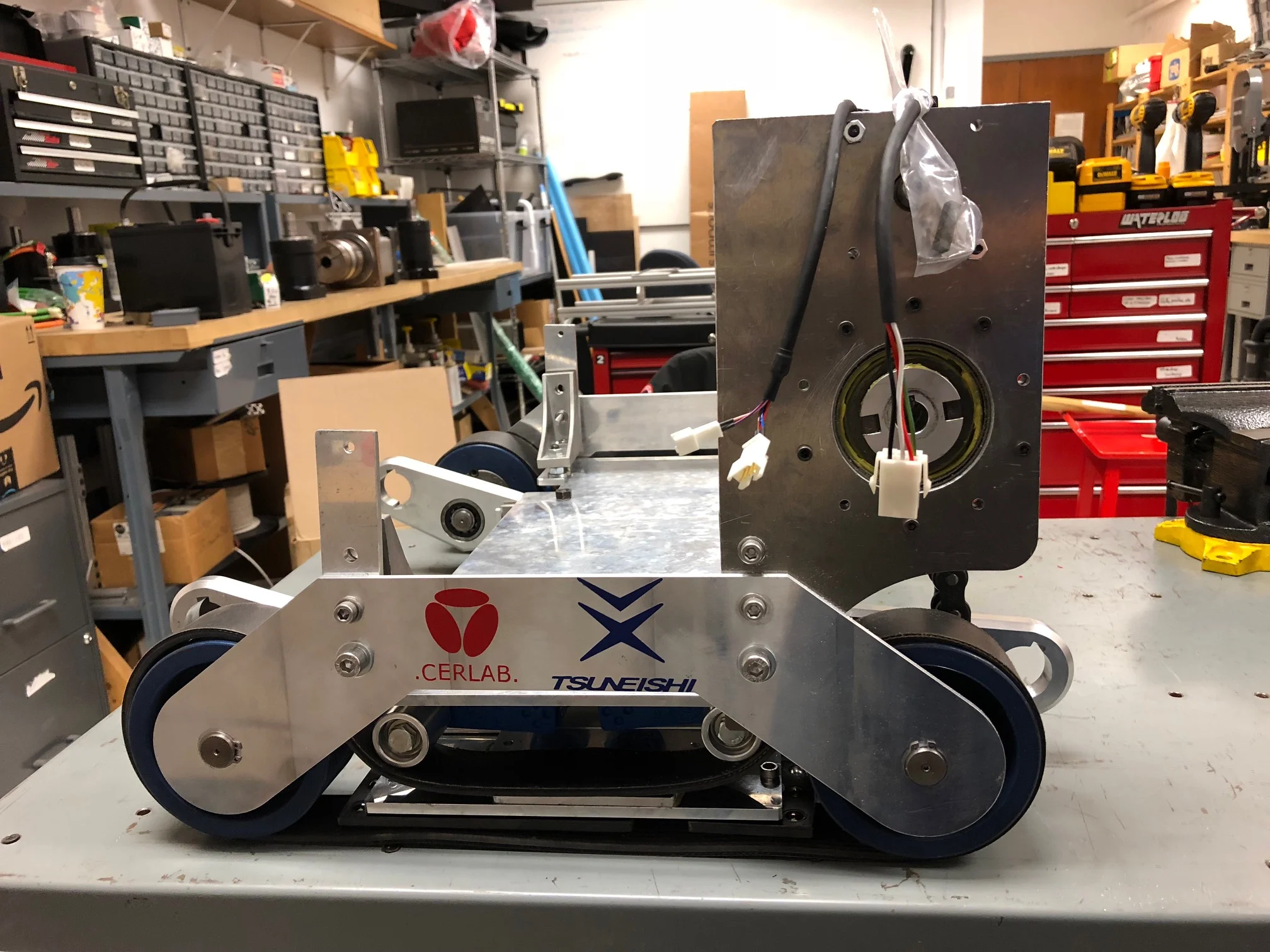
We decided on the basic main body + two arms assembly with the belt drive being the main transportation system
As shown on the left, the robot would have:
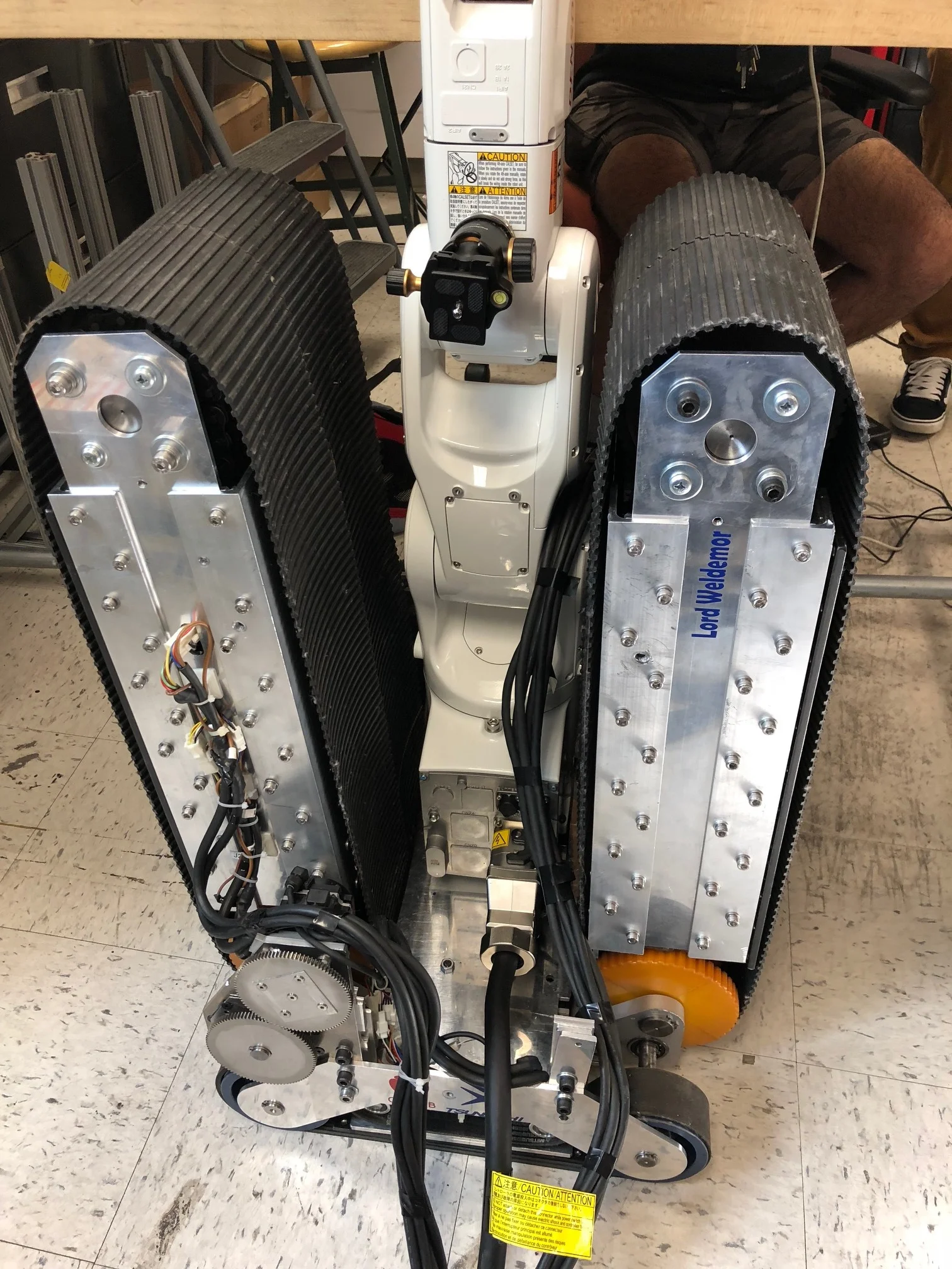
One Main body which carries a Denso robotic arm and Lidar, there would also be two belts running through both sides
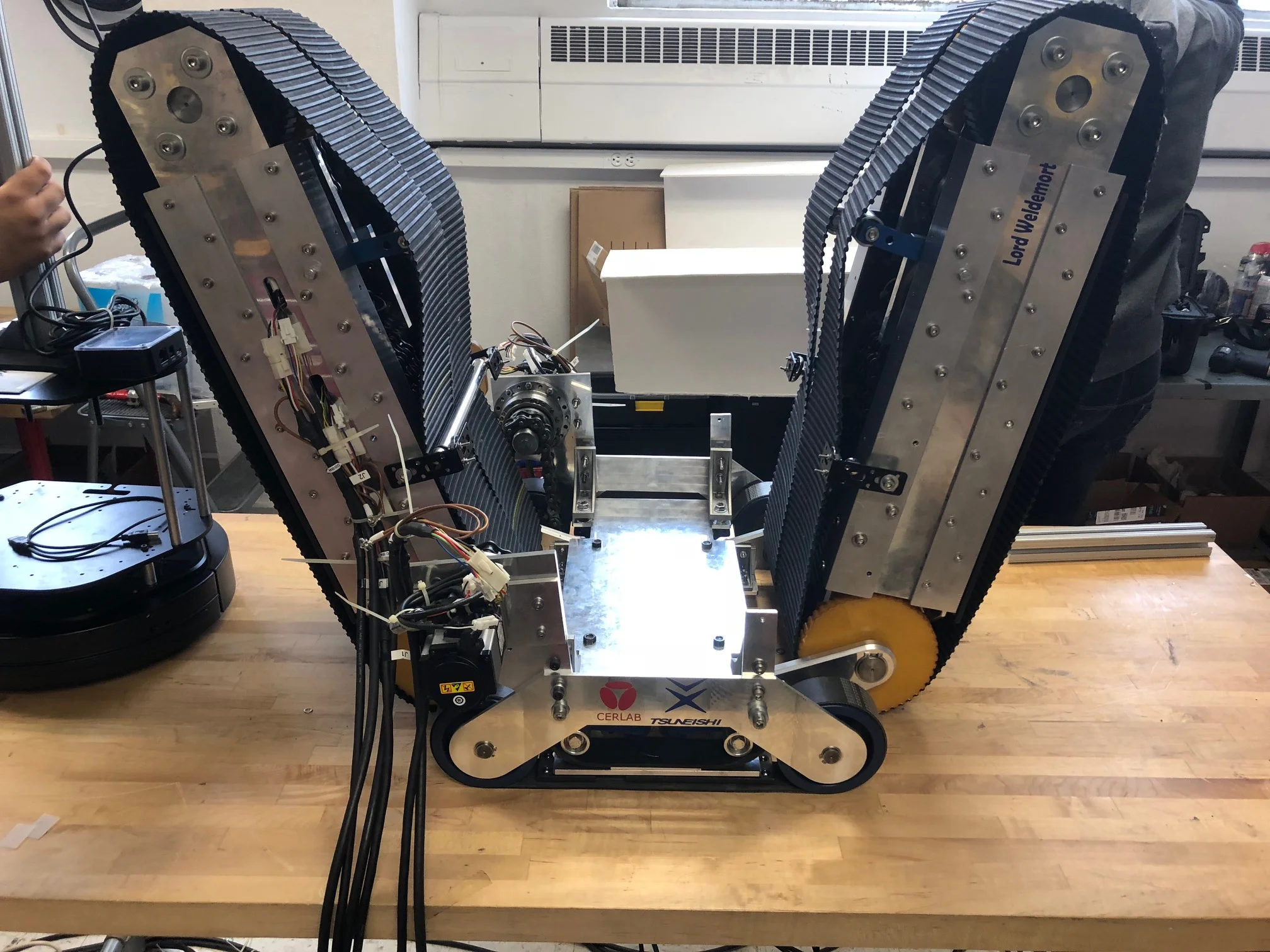
Two arms pivoting to push robots up and through the longis and manhole, each arm has timing belts rotating around to assist with the mobility

Map generated from Lidar
PerCeption + Welding
Use a denso robot arm to carry the welding tip
Offer great accuracy and large range of motion
Use a velodyne lidar for perception
Lidar generates 3D surrounding map
Localization algorithm to locate the robot and navigate

CAD for the robot in early stage
How it navigates
As shown by the images below, the robot fully utilizes its two arms to navigate inside the ship

My responsibility
I was responsible for the mobility system development
Belt Choice and Design
Suggested we went with the belt and drum combination
Studied which type of belt + drum combination works the best for arm drive and body drive
Decided to use flat belt with groves inside and double sided timing belt for the main body and arm drive
Fixture and structure design/analysis
Designed side panel and side plate to mount the motors and harmonic drive in Solidworks
Helped arranging the placement of motor, chain drive and mounting plates
Perform FEA on components to ensure strength with Solidworks and Ansys
Prototyping, Manufacturing and testing
Programmed CAM files for CNC of multiple parts
Selected catalog components for prototyping
Designed testing equipment/setup to test the robot