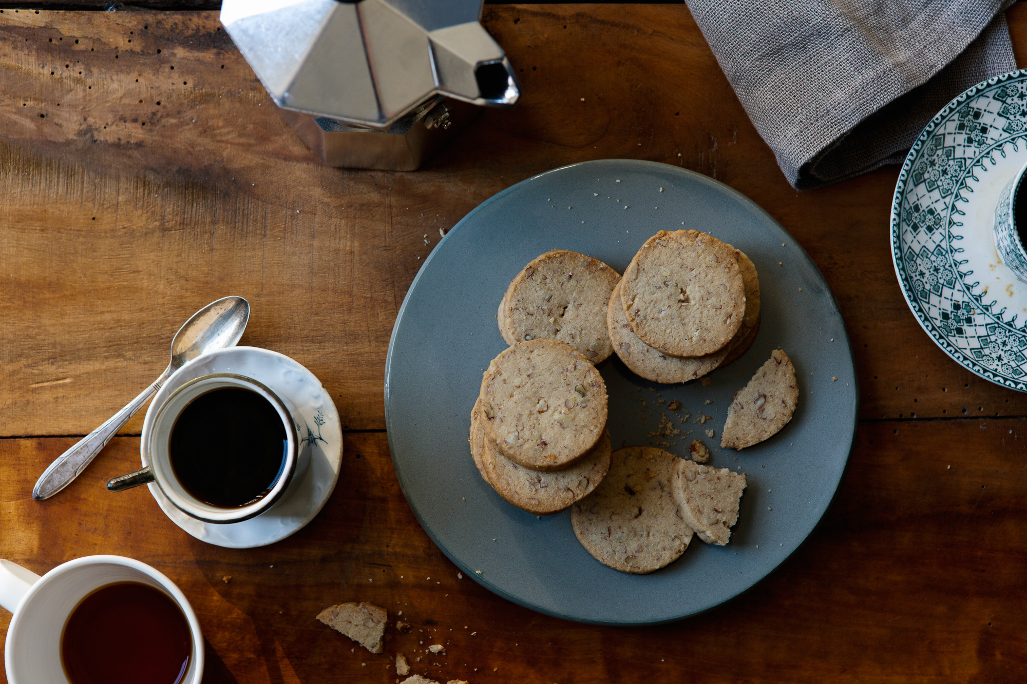
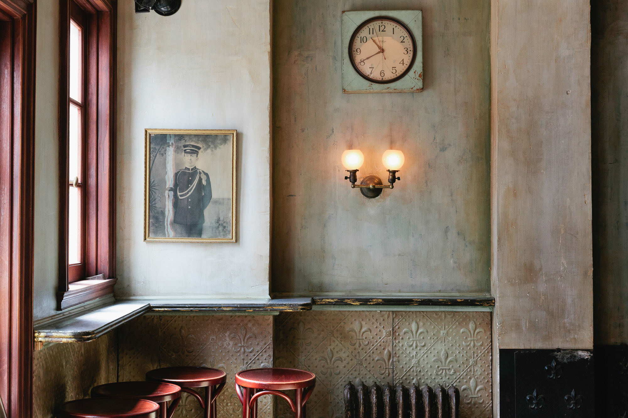
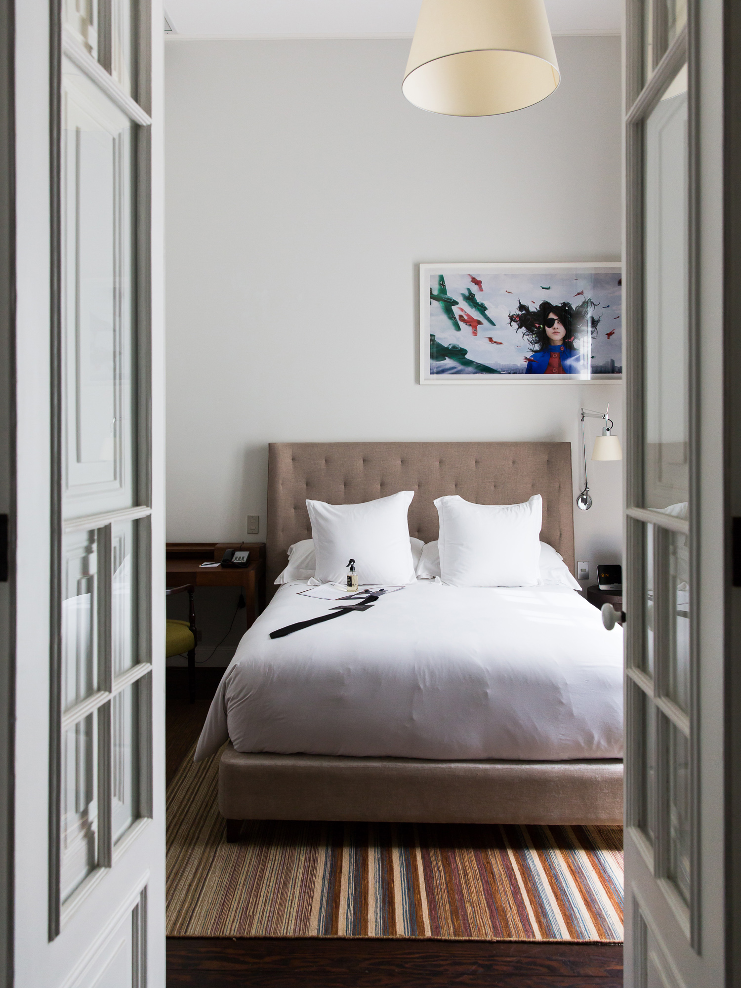
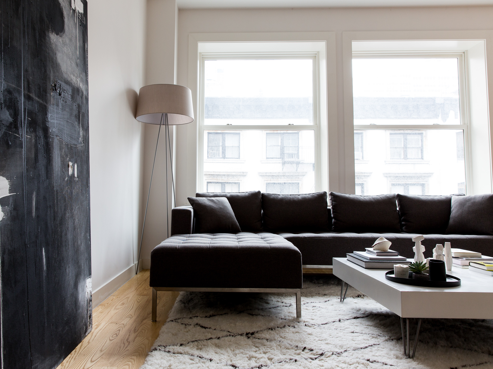
Sample photos

Photography legitimately taken by iPhone. Content for stress purposes only.
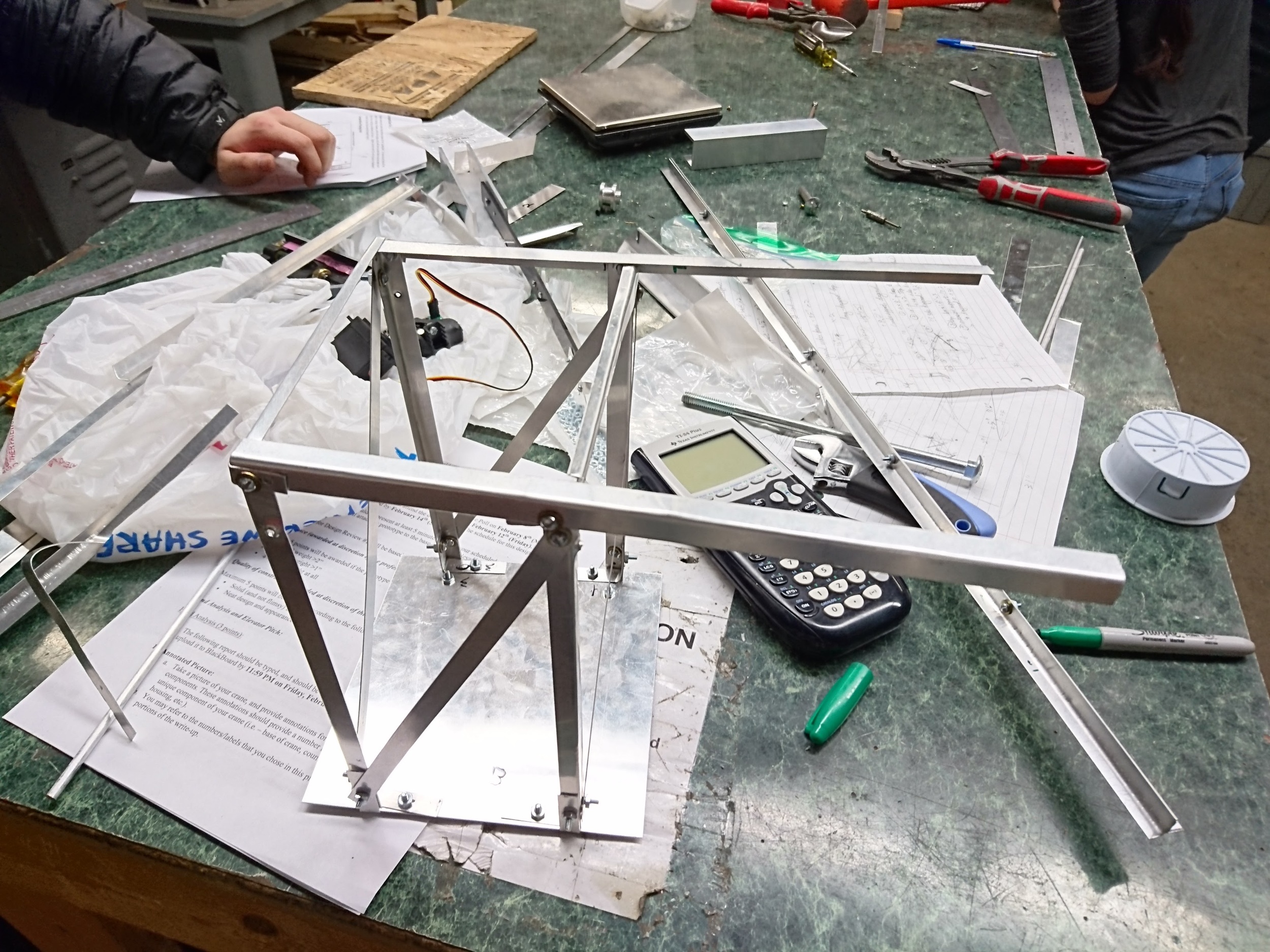
 

BASE

From Vancouver to Pittsburgh, we have come a long way to build a solid, minimalist base that is resistant to bending/twisting moment acting on the extended arm.  

ARMs

As you can see, we totally didn't waste the extended arm that doesn't have any attachment to it. This is a design style decided by the fact that we don't have a long enough aluminum arm.

Lima01.jpg

Forearm

With realistic design for our forearm attached to the motor, the chunk of aluminum that acts as the counterweight makes huge 10%  contribution to our bending torque.

WHY T?


The arm is a T-beam, formed by joining 2 L-beams using bolts.  The T-beam allows for high second moment of inertia, which would reduce bending.  While a T-beam is weak to torsion, our design intends to minimize twisting moment by having the load as close to the center axis of rotation as possible.

Even though the T-shaped arm is weak to torsion, we still chose it since it's easier to attach extra support to the flat bottom and attach our motor right in the center so that the total force acting down close to the center of cross section

 
T-shaped cross-section 

T-shaped cross-section 

side-view of how motor/forearm/arm are assembled together

side-view of how motor/forearm/arm are assembled together

WHY 8:4 ?


The motor turns a lever arm that is attached to the 1lb weight via a freely-spinning hook.  The other side of the lever arm houses a counterweight to reduce the torque that the motor needed to generate (by our calculations, only 73.7% of its total torque). The counterweight has multiple holes drilled into it for distance adjustment during the testing period.  We ultimately settled with the shortest length in order to not hit the ground when the motor turns to near 90 degrees.


The ratio of lever arm: lifting arm is 8:4 

The ratio of lever arm: lifting arm is 8:4 

As you can see, the motor is attached in between two pieces that forms the T-shaped arm

As you can see, the motor is attached in between two pieces that forms the T-shaped arm

WHY TRUSS ?


The base is a rectangular prism with an overhang.  The rectangular prism is made using L-beams to prevent buckling.  There is a baseplate for the prism, attached to the rest of the L-beams using L-shaped brackets.  The diagonals of the rectangular prism are supported to prevent distortions. 

The overhang on side is needed to attach the arm by 2 sets of bolts.  This allows the overhang to act as 2 pin supports for the arm.

.


front with support attachment

front with support attachment

back with diagonal pieces to distribute non-axial forces

back with diagonal pieces to distribute non-axial forces

All edges bent to enhance the base

All edges bent to enhance the base

WHY SUPPORTS?


After initial testing, we realized that the base itself is not enough to prevent the bending of the arm.  Therefore, we added 2 supports that extends from the bottom of the base, directly into the arm.  These are 2-force members that should cancel out each other in the horizontal forces, but provide vertical force components as additional pin supports for the arm.  In addition, the longest support was raised higher than the arm on purpose so that the arm, when not loaded, would be on a positive incline.  When the crane is under loading, the arm would still deflect downwards, but would remain, for all intents and purposes, horizontal.


Flattened end of L-arm support so that we can attach easily to the arm 

Flattened end of L-arm support so that we can attach easily to the arm 

Side-view of two L-arm supports 

Side-view of two L-arm supports 

Ignore the red hand, focus on the awesome supports

Ignore the red hand, focus on the awesome supports